
Die ASIC-Ausleseelektronik
Der CIPix
Das CIPix Board
FPGA basierte Datenauslese des CIPix
Der CASCADE-Detektor wurde entwickelt, um höchste Zählraten auf großen Flächen bei gleichzeitig guter Ortsauflösung (= große Anzahl an Auslesekanälen) nachweisen zu können. Damit verschiebt sich der Engpass beim Nachweis von Neutronen von dem Detektor-Frontend hin zur Ausleseelektronik. Sie muß nun in der Lage sein, die hohen Zählraten auf der großen Anzahl von Ausleskanälen gleichzeitig verarbeiten zu können. Schließlich soll das Konzept des modular aufgebauten Detektors auch im Bereich der Elektronik fortgesetzt werden, um die Skalierbarkeit des Gesamtsystems beibehalten zu können.
Auch im Bereich der Ausleseelektronik profitiert der CASCADE-Detektor von Entwicklungen, die vor allem von der Hochenergiephysik an der Fakultät für Physik und Astronomie der Universität Heidelberg in den letzten Jahren vorangetrieben worden sind. So wurde von Daniel Baumeister, Sven Löchner und Uwe Stange am ASIC-Labor der Auslesechip CIPix entwickelt, der eine Weiterentwicklung des HELIX-Chips darstellt. Der CIPix wird vor allem von der Arbeitsgruppe Prof. Straumann an der Universität Zürich für die Auslese der inneren Proportionaldrahtkammer des H1-Detektors am DESY eingesetzt. Durch den Einsatz des CIPix für die Ausleseelektronik verfügt der CASCADE-Detektor über ein bisher in der Neutronenphysik unerreichtes Leistungsniveau in Punkto Miniaturisierung, Anzahl der Auslesekanäle, Ratentauglichkeit und Kosten.
Der CIPix
Der CIPix besteht aus 64 analogen Eingangskanälen, die jeweils aus einem rauscharmen, ladungsempfindlichen Vorverstärker, einem Shaper, einem Buffer und einem Diskriminator aufgebaut sind. Je vier Ausgangskanäle werden von dem nachgeschalteten Multiplexer zusammengefaßt und zeitlich hintereinander auf einen der 16 digitalen Ausgänge gegeben. Über eine I2C-Schnittstelle kann der CIPix programmiert werden, d.h. die internen Register des Chips beschrieben bzw. ausgelesen werden.
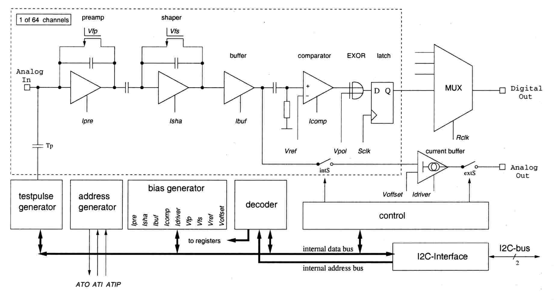 |
Das interne Blockschaltbild des Auslesechips für nur einen der 64 Kanäle auf dem CIPix. |
Das CIPix Board
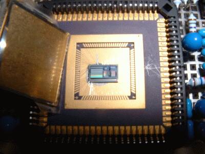 |
Blick auf einen CIPix 1.1 gebondet in ein Package. |
Bisher wurde mit Hilfe eines ersten Testboards der Chip in Betrieb genommen. Aufgrund dieser ersten Erfahrungen wurde in Zusammenarbeit mit Herrn A. Rausch und der elektronischen Werkstatt des Physikalischen Instituts ein professionelles Design für das CIPix Board entwickelt. In Kombination mit diesem Board konnte der CIPix inzwischen zusammen mit mehreren CASCADE-Neutronendetektoren getestet werden.
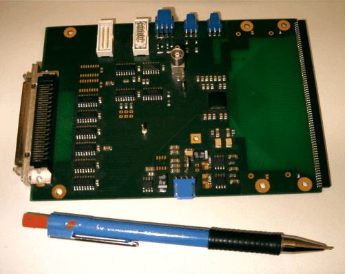 Erste Version des CIPix Board. |
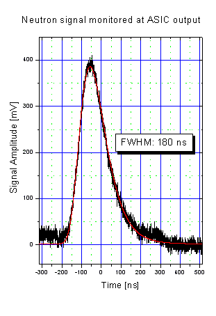 Typische Signalpulse gemessen am analogen Ausgang des ASIC. |
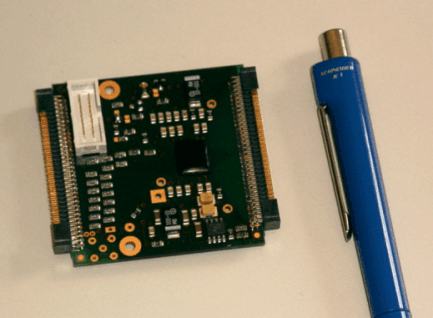 Unsere aktuelle Version des CIPix Board. |
Anfang 2004 ist das CIPix Board nocheinmal redesigned worden (hauptsächlich in Bezug auf seine Größe) und ist nun inzwischen verfügbar. Es wird nun bei der Auslese des neuen 2D-Detektors eingesetzt werden. Dieser Detektor besitzt eine sensitive Nachweisfläche von 20cm x 20cm mit 128 Auslesekanälen in x-Richtung und 128 Kanälen in y-Richtung. Diese Auslesekanäle werden von 4 CIPix-Chips ausgelesen. Dieser Detektor soll noch in diesem Sommer getestet werden. |
FPGA basierte Datenauslese des CIPix
Aufgrund der großen Bandbreite an Daten, die der CIPix Chip produziert (64 Auslesekanäle feuern je mit einer Maximalrate von 10 MHz pro Kanal), ist ein echtes Realtime-System notwendig, um all diese Daten verabeiten zu können. FPGA's sind für diese Aufgabe sehr gut geeignet und können benutzt werden, um die digitalen Signale des CIPix zu demultiplexen und die Neutronenereignisse in Bezug auf Ort und Zeitpunkt zu rekonstruieren. Weiterhin können die relevanten Histogramme bereits im FPGA erstellt und in geeignetem zusätzlichen Speicher hinterlegt werden. Alternativ können die Daten aber auch direkt an ein weiteres angeschlossenes Backend-System gesandt werden (Event-Daten).
Nachdem der CIPix mit dem ersten Board zur Verfügung gestanden hatte, konnte die gesamte Kette der Datenaufnahme bereits 2003 erfolgreich während einer Strahlzeit am ILL getestet werden. Die gesamte Kette bestand aus einem CASCADE-Detektor, der mit einem CIPix Board ausgestattet war, einem FPGA Board für die Datenanalyse und -kompression und dem Transfer der Daten via VME zu einem PC.
Basierend auf diesen Erfahrungen wurde inzwischen ein neues FPGA Board entwickelt und produziert (siehe die nächsten beiden Bilder weiter unten). Ausgestattet mit einem 'VIRTEX II' FPGA von Xilinx können nun nun alle 4 CIPix Boards des neuen 2D-CASCADE Detektors simultan ausgelesen werden. Dabei führt der FPGA die vollständige Eventrekonstruktion (Ort und Zeit) durch als auch die Ansteuerung der 4 CIPix Boards. Zusätzlich befinden sich auf dem FPGA-Board SRAM und 1GB an DDR-RAM, um alle anfallenden Daten lokal am Detektor in jedem gewünschten Format abspeichern zu können. Die abschließende Datenübertragung zu einem PC oder einer Workstation erfolgt über einen optischen Link (1GBit/s), sodaß die gesamte Auslese-Elektronik, die ja direkt auf der Rückseite des Detektors sich befindet, vollständig galvanisch von jeder weiteren Steuerelektronik eines Instruments getrennt ist.
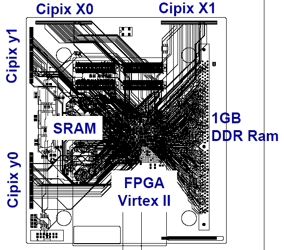 Schema des neuen FPGA-Boards für die Auslese des 2D CASCADE Detektors. Ein 'VIRTEX II' FPGA von Xilinx wird zur Eventrekonstruktion und zur CIPix-Ansteuerung benutzt. SRAM und DDR-RAM on board ermöglichen die lokale Speicherung aller Daten am Detektor. |
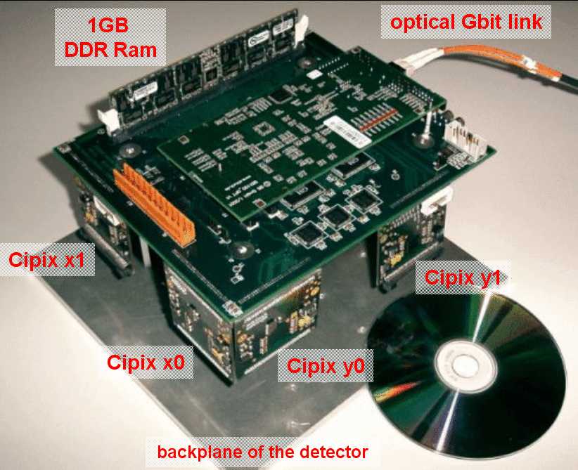 Photo des neuen FPGA-Boards. Die gesamte Auslese-Elektronik sitzt direkt auf der Rückseite des Detektors. Daten, die von der Auslesestruktur des Detektors kommen, werden verstärkt, digitalisiert und weiter zum FPGA geleitet. Abschließend können die Daten lokal im SRAM und gleichzeitig im DDR-RAM gespeichert werden oder alternativ direkt zum PC über einen optischen Link gesandt werden. |
ASIC-FPGA Auslese-Elektronik
- 4 CIPix Chips mit insgesamt 128x128 Auslesekanälen
- FPGA basierte Datenverabeitung und -kompression
- on board Speicher: DDR-RAM für 256 Mio. Counter, d.h. 16k Pixel mit je 16k Timebins
- Echtes online monitoring (SRAM): 1 Mio. Counter frei konfigurierbar: z.B.
- 128 Pixel (statisch, alle Zeitkanäle aufintegriert)
- 128 Pixel mit einem TOF-Fenster zwischen 10ms und 11ms (alle Daten aufintegriert)
- Datentransfer zu PC/Workstation via optischem GBit Link
