
Manufacturing Steps for a CASCADE-Detector Module
Currently employed GEM foils
High voltage conditioning
Coating with Boron
Mechanical tension on GEM foils
CASCADE GEM-module
Final CASCADE detector module
A CASCADE detector is built up of a stack of Boron coated GEM-foils, called GEM-modules.
Charges generated by neutron absorption fragments on either side of any GEM-foil in a
counting gas are channeled successively through the entire cascade of GEMs onto a readout
structure by means of suitable electric fields between adjacent GEMs. Every GEM-module
consists of a GEM spanned onto a narrow spacer frame. Assembled in a CASCADE-stack,
the detector inside is sealed gas tight to the outside. The entire stack of GEMs is
sandwiched between a Boron coated drift electrode and the readout structure. Depending
upon specific detection needs, any number of GEM-modules can be used, ten are needed to obtain
50% detection efficiency for thermal neutrons.
The GEM-module
closest to the readout structure can be operated in its actual electron mulitplying
mode, as to give an additional ultra-low noise preamplification of gain 10 to 100. In
case of any defecting GEM, the corresponding GEM-module can easily be replaced by a spare,
so that the detector would be up and running again within a couple of hours.
Below, a short tour through the CASCADE manufacturing process is presented as it is performed today. In particular with respect to the mechanical stretching and glueing procedure, the CASCADE group inherited an entire universe of know-how developed by the Heidelberg HERA-B-Group of Prof. Eisele`s. This estimated 50 man-years worth of research and development for the Hera-B inner tracker detector serves as a basis for the CASCADE effort. More than 200 HERA-B GEM-detector modules were manufactured at the Physics Department of Heidelberg and give an impressive prove of the series-production feasibility for such a detector concept. Naturally, production of CASCADE GEM-modules and detectors foods on this experience and develped further on from there.
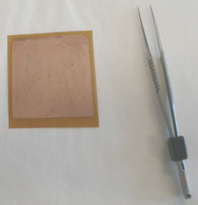 active GEM-area about 5 cm x 5 cm |
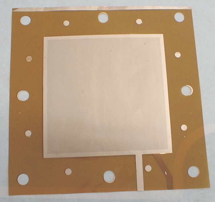 active GEM-area about 10 cm x 10 cm |
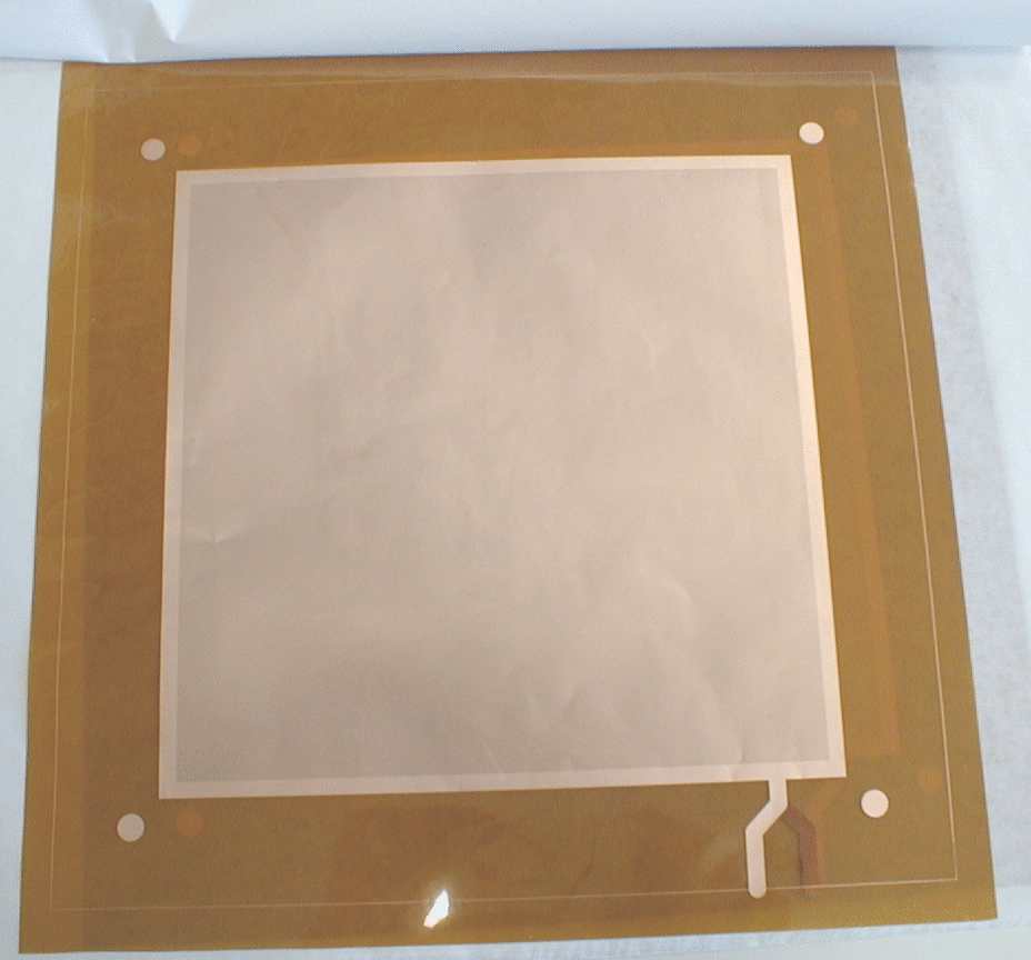 active GEM-area about 20 cm x 20 cm |
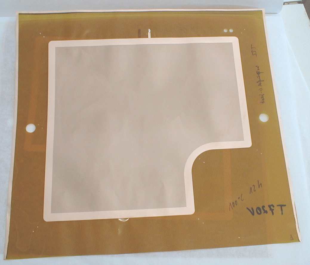 active GEM area 25 cm x 25 cm (HERA-B-geometry, leaving room for the beamline) |
GEM-HV-Conditioning
| Newly received GEM-foils do not come with any particular high voltage stability. They need to undergo a complicated, extensive break-in procedure that gets them adapted to withstand highest possible potential differences. This procedure is called conditioning. A virgin GEM, driven to its operating potentials through a period of several minutes will most probably generate a spark even during the ramp, rendering the foil with a short and degraded to an ordinary sieve. Properly conditioned GEMs on the other side turn out to be enormously robust. High voltage can be applied in steep ramps thereon. One entire detector even survived a sudden power failure and the "inevitable" sudden return of power without damage. | 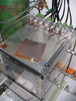 Flowbox for the automated conditioning of more than ten GEM-foils in parallel under a protective atmosphere. |
Coating with Boron
 GEM coated with about 650nm of 10Boron neutron converter |
Various industrial coating processes for Boron turned out
unsuitable for GEMs due to the high process temperatures involved. Currently,
Boron is deposited onto the GEMs by means of electron beam evaporation. Tedious development allowed to evaporatively coat the GEMs without compromising high voltage properties. |
Mechanical Tension on GEM-Folien
| Highest possible electric field homogeneity is achieved by glueing individual GEMs under a considerable tension onto the module frames. A special tool allows to maintain the tension even during a glue bakeout step until the bond is cured. |
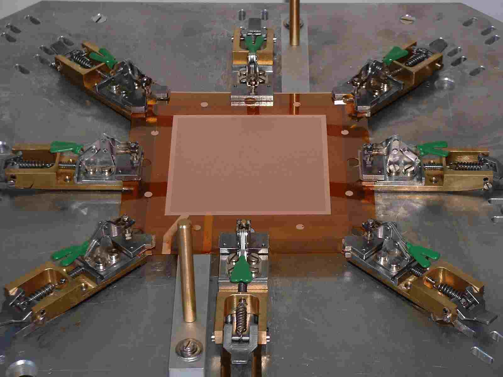 GEM-foil extended under tension in preparation to be glued onto a module frame. |
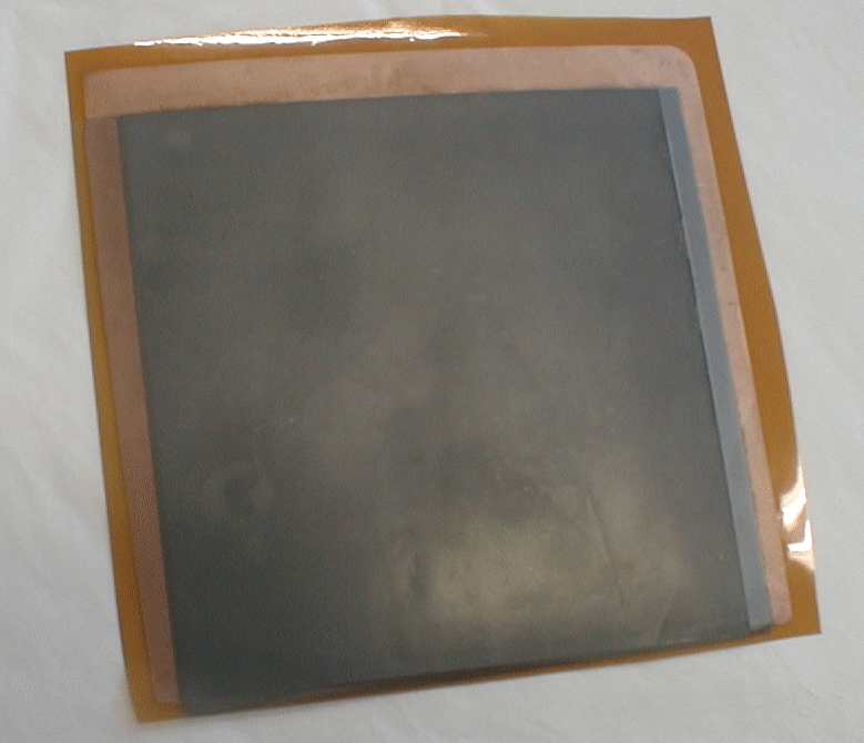
GEM-Module
| This photo shows a completed GEM-Modul: A foil that was glued onto a module frame (coating was omitted in this case) | 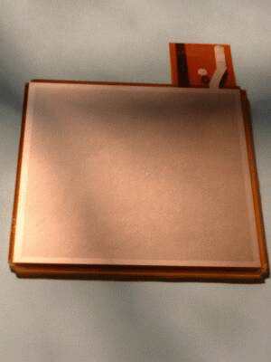 |
CASCADE Detector-Module
 |
10 GEM-modules are stacked together. 5 modules on each side of the readout structure. The stack is attached to an Aluminium backing plate that holds the necessary infrastructure such as connectors for the continuously purged counting gas, a high voltage connector, EMI-protective HV-filters as well as the preamp electronics, the ASIC CIPix. The prototype on this photo is a 100mm x 100mm module which was tested at the ILL/Grenoble. |
The manufacturing procedures and the mechanical layout are currently under continuous improvement towards a stable, robust and easy to service detector design and production scenario. The module sensitive area is now extended to sizes of 200mm x 200mm and will be extended further to 300mm x 300mm or even larger.
The CASCADE group supports Diploma- and PhD-theses, Practicals and other interested students to participate in this exciting project. For information please do not hesitate to contact at home of CASCADE directly.