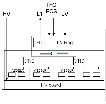
Schematical layout of the electroncis box.
The interface to the module is provided by the feed-through cards: The feed-through cards carry connectors for the signals and provide solid ground connections to the subsequent cards by a gold plated spring contact. The pasive cards are intergral part of the module and cannot be replaced.
The HV boards are the next cards which
follow in the signal chain: They provide the HV to the anode wires
and decouple the signals using embedded
capacitors. We foresee one HV board for 32 channels, thus
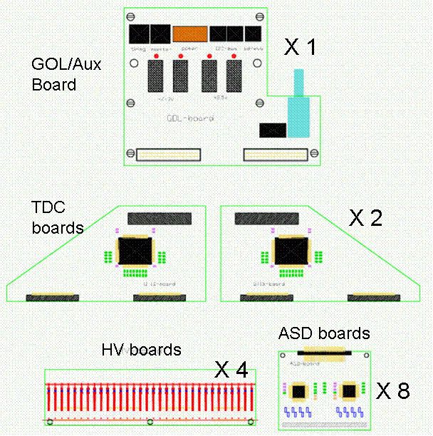
4 HV boards are necessary to equip the
128 channels of one module end.
The modularity of the HV distribution
is currently discussed. The base-line is to supply the channels of the
two module layers separately.
The next element in the signal chain are
the amplifier-discriminator (ASD) cards. An ASD card carries
two 8-channel ASD-BLR chips. The cards
are plugged to the HV boards.,
The outputs of always 2 ASD cards (=32 channels) are fed to the TDC cards based on the OTIS chip. The TDC cards also provide power and the threshold voltage to the ASD cards.
The 4 TDC (OTIS) cards per module-end are
connected to the GOL board: this board carries a radiation
hard serializer chip, the optical
link components, low-voltage regulators, a QPLL chip to provide
a stable
BX clock and the Slow Control interface.

Schematical layout of the electroncis box.

Different electronic cards.
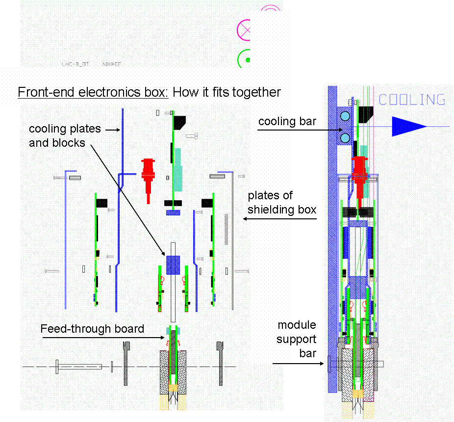
The above cards all have to fit into a tight metal box of 22x30x4cm. The metal cover of the box is used to shield the electronics, in particular the amplifier cards. The complete enclosure of the electronics prevents the cooling of the electronic cards by air flow. An estimate of the power dissipation has revealed a heat development of about 22 W per box which enforces active cooling of the most dissipating components. We therefore foresee to mount cooling plates attached to water cooled bars (see Figure below).
An important design constraint for the box layout is the maintainability: easy echange of all components, including the HV board must be possible. The current station layout foresees that always two stereo-layers are moved out together from their nominal positions to the maintenance positions. This simplifies the access to the electronics. All electronics boxes are accessible from the front. The boxes are opened by removing the cover plate and the components can be dismantled one by one.
An additional constraint to the box-layout comes from the gas-supply
pipes. A total of four pipes, 2 pipes for each the inner and the
outer volume, must enter into the module. To keep the pipes
out of the electronics box they enter the module at the sides.
As a result, the designs of the feed-through cards and the HV cards
must account for the slightly narrower space.

Electronic components
and their assembly to the electroncis box.