The LHCb Outer Tracking gas system
The gas system for the LHCb Outer Tracker is described in detail in the EDMS document No. 414246.v4.0.The design parameters for the gas system are
| Gas mixture | Ar/CO2 70%/30% |
| Total volume | 3.7m3 |
| Total nom. circulation flow | ~ 3.2 m3/h |
| Max. circulation flow: | ~ 5.0 m3/h |
| Nominal replenishing flow | ~ 0.1 to 0.2 m3/h |
| Max. replenishing flow | 0.8 m3/h |
| Chamber pressure | 0.5 - 2.0 mbar |
| Hydrostatic Diff. | ~ 0.5 mbar |
| Max. overpressure | 5 mbar |
| No. of Channels | 36 |
| No. of Sub-Dis. Units | 2 |
| No. of UX Racks | 2 |
| Impurities | O2 < 100ppm; H2O < 100 ppm |
The schematic layout of the LHCb Outer Tracker gas system is the following (all drawings on this site are taken from the EDMS document cited above):
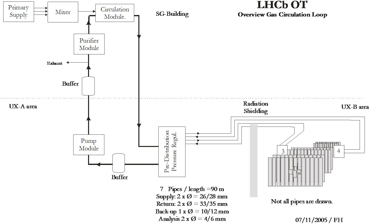
k The nominal running mode for the Outer Tracker is the fill mode (open circulation), but it can also be run in the run mode (re-circulation).
There are three location for the components of the OT GS:
- Mixer module, circulation (exhaust) module and purifier module are located in the SG building at the surface.
- Pre-distribution module and pump module is in UXA, i.e. it can be accessed during LHC running.
- The distribution modules are in UXB under the bunker, i.e. they can not be accessed during LHC running.
The mixer module
The mixer module allows to provide a trinary gas mixture for the LHCb Outer Tracker. The 3 lines are foreseen for Argon, CO2 and CF4. The schematics for the mixer module is shown here: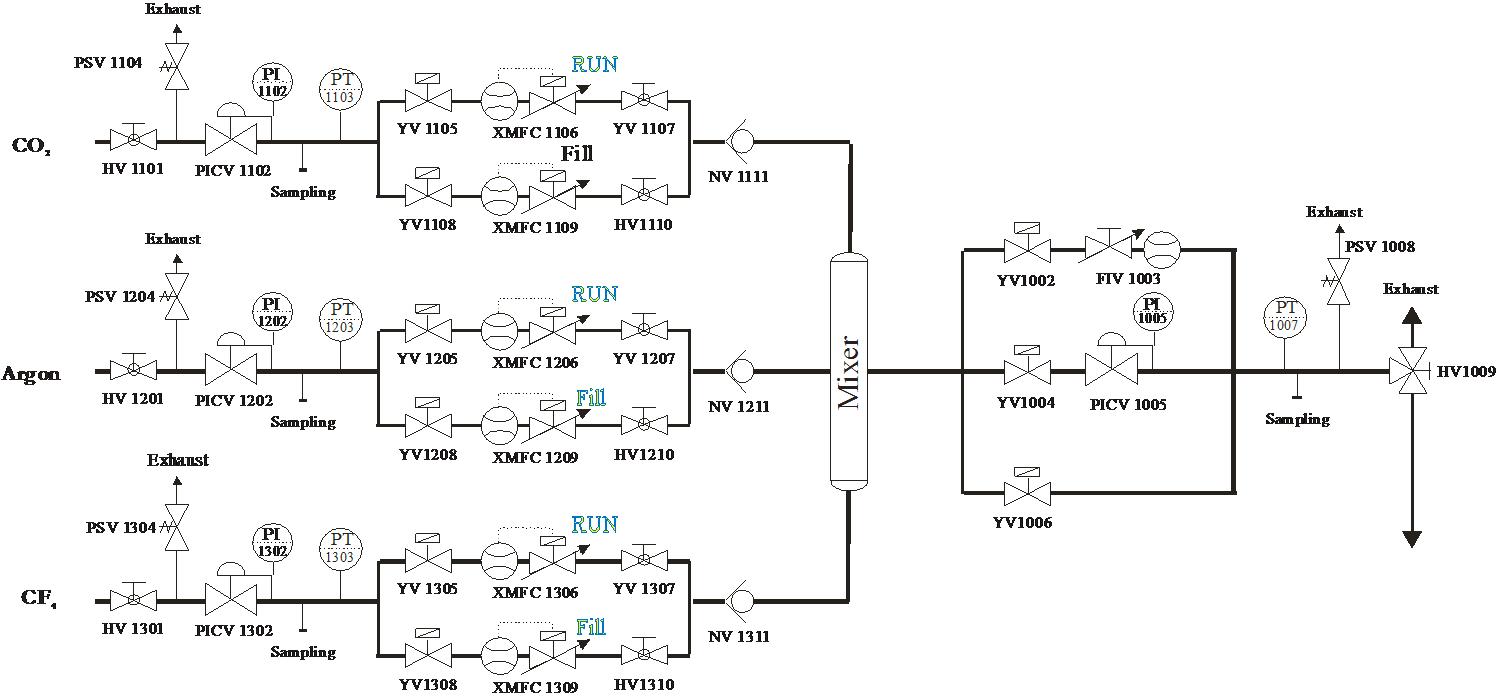
Circulation or exhaust module
The circulation (often called exhaust) module collects the gas from the mixer and sends it down to the pre-distribution rack in UXB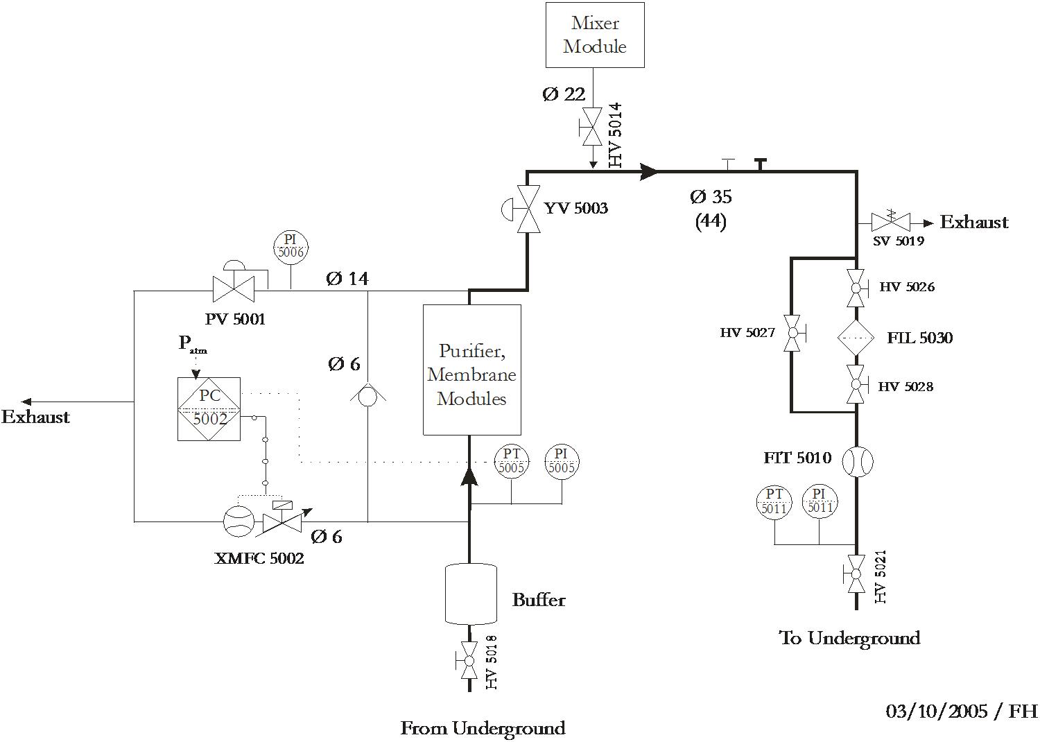
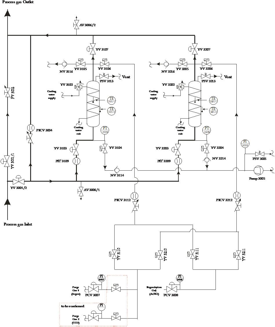
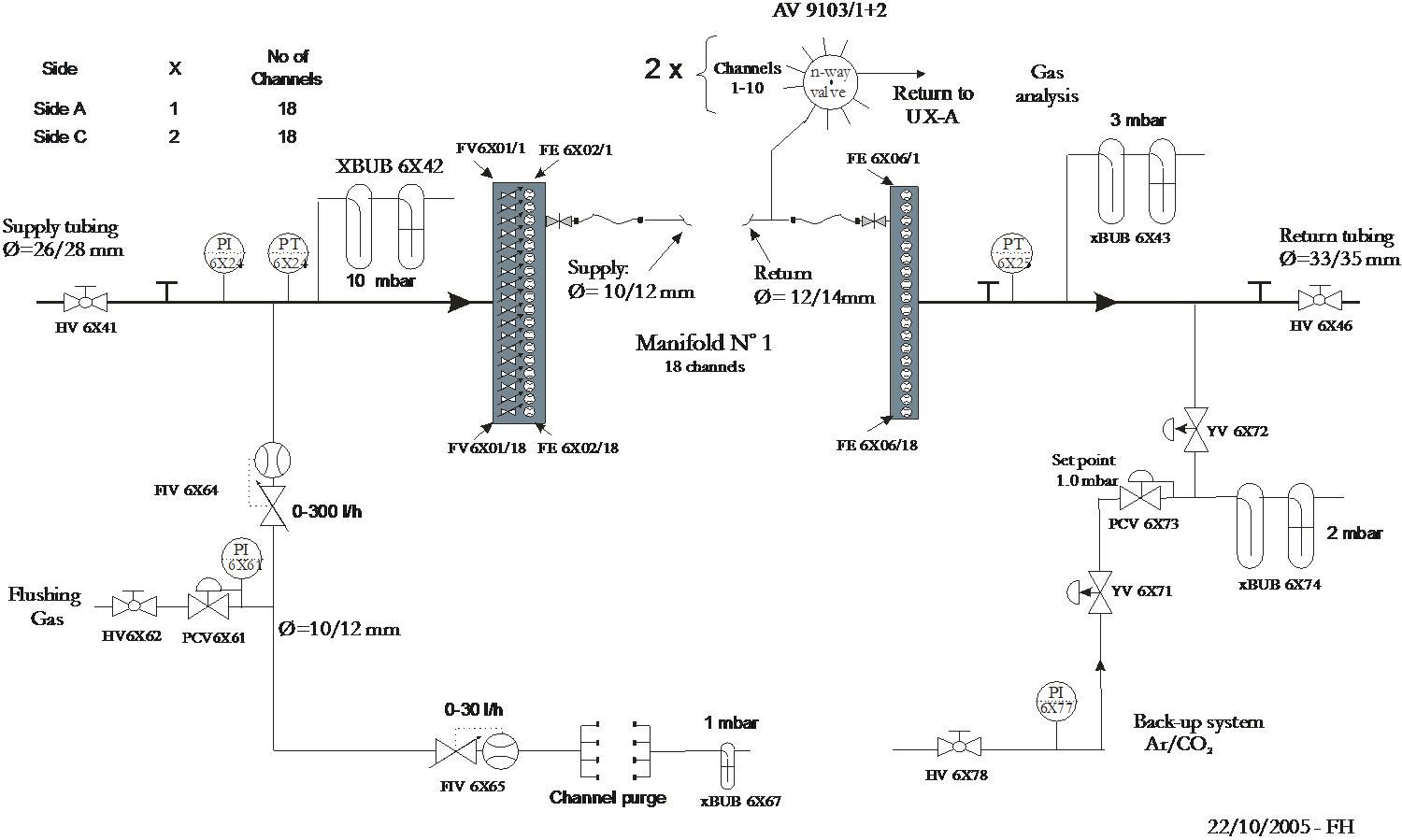
The gas distribution
The gas distribution is divided into the pre-distribution module at UXA. In the pre-sistribution rack the pressure is reduced from the high pressure (~0.6bar) in the preceeding modules to a few millibar. This is done by the Zimerli pressure regulator PCV6121. This pressure defines in combination with the total gas flow and the impedance of the pipes between UXA and UXB the pressure in the distribution rack as measured by PT6x24. This pressure is one of the parameters defining the gas flow through the detector modules.In the pre-distribution rack the gas lines are split in two lines serving the distribution racks for the A-side and the C-side placed in UXB. Each of the two distribution racks has 18 channels going to the detectors. The assignment between the channels of the distribution rack and the detector modules is described in here. From the detectors the gas is sent back to the distribution racks from where it is sent back to the pre-distribution rack in UXA. The pre-distribution outlet leads to the pump module. Schematic views of the pre-distribution and distribution racks are shown below:
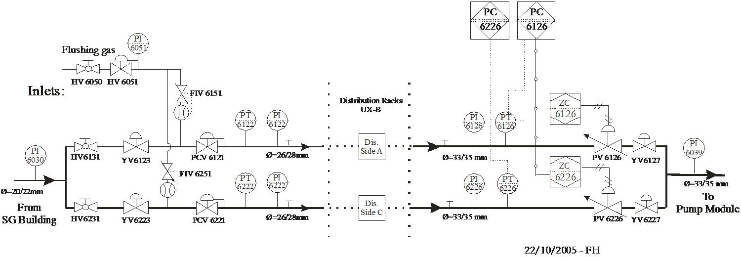
The gas flow is determined by 3 factors:
- The pressure difference between the input and the output as measured by PT6x24 and PT6x25. The pressure at PT6x24 can be adjusted manualy by the Zimerli pressure regulator PCV6121 in the pre-distribution rack. The setting point of the control valve PV6126 defines the pressure on the output. Typically this pressure is set to a slight over pressure of ~0.3mbar to 1.0mbar.
- The impedance of the detector modules and the impedance of the control valve FV6x01/1 that can be adjusted manually. While the Zimerli pressure regulator can be accessed during LHC runs, the control valve FV6x01/1 can not.
- The total flow is limited by the flow defined as setting point for the mass flow controller XMFC1101 for the CO2 line in the mixer module and the demand for the correct ratio of the gas components guaranteed by the regulation of the mass flow controller XMFC1301 and XMFC1201 (if applicable). In case the system demands less gas compared to the setting point on XMFC1301 only the amount of gas needed is provided. If the system demands more than this the gas flow is limited by the setting point.
- Filters have been installed at the input of the distribution racks. They filter all dust particles with a size exceeding 5µm. The filters used are described here,
- A bypass has included before the distribution racks. They allow to purge the detectors using the flushing line in the distribution rack on one hand and to operate at the same time the gas system bypassing the distribution racks. This is useful when maintenance work has to be performed on the gas system, but the flushing should not be interrupted by this.
Pump module
The gas is collected from the pre-distribution rack. At the input of the pump the pressure is negative at about -5mbar. The pump compresses the gas to a pressure of about 0.6bar and sends the gas back to the circulation module at the surface. Depending on the running mode all gas is purged from here (fill or open mode) or most of the gas is sent to the purifier module (re-circulating mode) while only part of the gas (defined by the replinishing flow) is purged. The purged gas is substituted by the mixing module.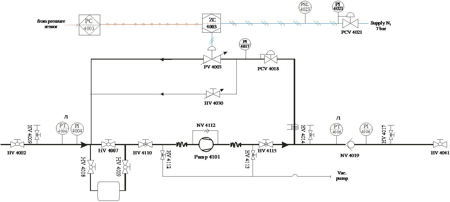
Purifier module
The default for the OT is to run in the fill (non-circulating or open) mode. Therefore the purifier is not used in the standard configuration.