Version  0.03    2002.11.04    dg/kip


DCS to Read Out Board 

               A DIMM144 connector / horizontal / SMD is provided for connection.

               2x2x8 bidirectional chains for DCS link rings / LVDS
               3x8 control lines for voltage regulators
               max. 8 clock distribution lines / differential ?
               (1? reset line / to be defined)
               
               
               min. 24 x GND (digital )
               4 GND connection control lines for grounding quality monitoring
               6 pins for main supply ( 4 Volts ) for DCS board
               
               DIMM 144 connector datasheets : Fujitsu  ;  JAE  ;  DDK socket / footprint / module
               Orcad DIMM144 horizontal SMD part definition (dg)


Page 1     back to content


System Overview

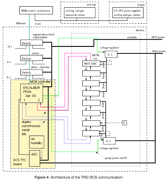
   In figure 4 only one data chain is shown. At least 8 data chains have to be served by one DCS
   board.  Each chain consists of to antiparallel lines which in turn consist of a differential cable pair.
   So at least 16 inputs and 16 outputs are required. The two antiparallel data chains are for
   redundancy. If the chain is broken at one point all clients can still be served by the DCS board
   because all clients are
accessible by two sides.

   For more details see TRD document

Page 2     back to content


DIMM 144 connector pinout ( preliminary )

1

GND


2

GND

3

DCS downlink 1n (LVDS)


4

DCS downlink 1p (LVDS)

5

GND


6

GND

7

DCS downlink 2n (LVDS)


8

DCS downlink 2p (LVDS)

9

GND


10

GND

11

DCS downlink 3n (LVDS)


12

DCS downlink 3p (LVDS)

13

 GND


14

 GND

15

DCS downlink 4n (LVDS)


16

DCS downlink 4p (LVDS)

17

 GND


18

 GND

19

DCS downlink 5n (LVDS)


20

DCS downlink 5p (LVDS)

21

GND


22

GND

23

DCS downlink 6n (LVDS)


24

DCS downlink 6p (LVDS)

25

GND


26

GND

27

DCS downlink 7n (LVDS)


28

DCS downlink 7p (LVDS)

29

GND


30

GND

31

DCS downlink 8n (LVDS)


32

DCS downlink 8p (LVDS)

33

GND


34

GND

35

Clock 1p


36

Clock 2n

37

 Clock 1n


38

 Clock 2p

39

 GND


40

 GND

41

 GND


42

 GND

43

 Clock 3p


44

 Clock 4p

45

 Clock 3n


46

 Clock 4n

47

 GND


48

 GND

49

Vreg Shutdown 1


50

Vreg Shutdown 2

51

Vreg Shutdown 3


52

Vreg Shutdown 4

53

Vreg Shutdown 5


54

Vreg Shutdown 6

55

Vreg Shutdown 7


56

Vreg Shutdown 8

57

Vreg Shutdown 9


58

Vreg Shutdown 10

59

Vreg Shutdown 11


60

Vreg Shutdown 12

Page 3     back to content


3,3 Voltage Key Center


3,3 Voltage Key Center

61

Vreg Shutdown 13


62

Vreg Shutdown 14

63

Vreg Shutdown 15


64

Vreg Shutdown 16

65

Vreg Shutdown 17


66

Vreg Shutdown 18

67

Vreg Shutdown 19


68

Vreg Shutdown 20

69

Vreg Shutdown 21


70

Vreg Shutdown 22

71

Vreg Shutdown 23


72

Vreg Shutdown 24

73

GND


128

GND

75

+3,8V DCS Supply


130

+3,8V DCS Supply

77

+3,8V DCS Supply


132

+3,8V DCS Supply

79

+3,8V DCS Supply


134

+3,8V DCS Supply

81

GND


136

GND

83

GND


84

GND

85

GND


86

GND

87

reserved


88

reserved

89

reserved


90

reserved (RESET#)

91

GND


92

GND

93

GND sense 1


94

GND sense 2

95

GND sense 3


96

GND sense 4

97

GND


98

 GND

99


100


101


102


103


104


105


106


107


108


109

GND


100

GND

111

GND


112

GND

113

DCS uplink 8n (LVDS)


114

DCS uplink 8p (LVDS)

115

GND


116

GND

117

DCS uplink 7n (LVDS)


118

DCS uplink 7p (LVDS)

119

GND


120

GND

Page 4     back to content


121

 DCS uplink 6n (LVDS)


122

 DCS uplink 6p (LVDS)

123

GND


124

GND

125

DCS uplink 5n (LVDS)


126

DCS uplink 5p (LVDS)

127

GND


128

GND

129

DCS uplink 4n (LVDS)


130

DCS uplink 4p (LVDS)

131

GND


132

GND

133

DCS uplink 3n (LVDS)


134

DCS uplink 3p (LVDS)

135

GND


136

GND

137

DCS uplink 2n (LVDS)


138

DCS uplink 2p (LVDS)

139

GND


140

GND

141

DCS uplink 1n (LVDS)


142

DCS uplink 1p (LVDS)

143

GND


144

GND

      There are 24 shutdown lines on the DIMM connector for the voltage regulars / modules.
      These Vreg control lines switch of power on modules ( groups ) which behave strange.
      This should prevent modules/groups from drawing
excessive power and heating up the chamber.
      Module failure is especially expected because of radiation effects by high energy particles.

      Additionally maximum 8 clock lines have to be distributed by the DCS board. These clock lines
      require outstanding low jitter because of synchronisation demands.

Page 5     back to content