Version   0.02  2002.11.04  dg/kip

 
Clock Generation and Distribution

    The DCS board has to deliver appropriate clocks for the connected systems.
    These clock lines require outstanding low jitter because of synchronisation demands.
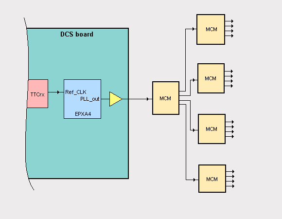
    The DCS board is fed by an optical master clock distribution system. A dedicated TTCrx chip
    will regenerate this clock and send it to the EPXA4 FPGA. The EPXA4 can multiply or divide
    the clock with internal PLLs to a wide range of possible frequencies.
    (  Further information about the TTCrx chip.

    Required clock frequency for the MCMs : 120 MHz
    Maximum trace length between FPGA and next MCM : ??
    Maximum trace length between MCMs : ??
    Maximum number of MCMs in a clock chain : ??
    Impedance matching : ??
    Clock jitter :  50 ps max. 


Page 1     back to content


    The clock is didtributed tree like. One clock line serves one MCM. Every MCM is able to serve
    four additional MCMs. This scheme reduces output load of the clock drivers but may introduce
    additional delays. Not more than 8 clock lines have to be driven by the DCS board.
    Maximum number of MCMs in a clock chain is ??.

    Structure of a clock distribution tree  
     Clock drivers like the PI49FCT3805 by Pericom or the IDT49FCT3805 by IDT can be
     used on the DCS board.

Page 2     back to content